For station automation it is quite useful to have some sort of band defining outputs from your radio. Most of the Yaesu transceivers offer BCD signals (binary coded data), the Elecraft K3 does so, too, while Icom has some band-voltage outputs. The only big brand that does not offer any kind of band identification at all is Kenwood. That’s a shame. As we are using a Kenwood TS-590 as one of our contest radios (they offer quite a good price-performance ratio) and all our automatic band filter & antenna switching is based on BCD signals we had to do something to automate things when using the Kenwood, too. Therefor I developed a CAT based banddecoder.
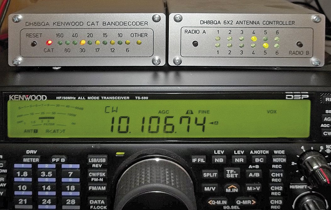 Left is the banddecoder, detecting the currently used band thru CAT and putting out BCD signals which in turn are triggering the 6×2 antenna controller right.
A detailed description can be found in FUNKAMATEUR magazine issue FA 10/13 in German language. Core of the design is a PIC 18F452 that offers (among other peripherals) a serial port that is used to do the CAT communication with the Kenwood TRX. TXD/RXD serial levels are real RS-232 thru a MAX 232, so you can directly connect it to the TS-590 or a TS-480, TS-570, TS-990, TS-2000, etc. The PIC asks the transceiver for it’s current frequency and puts out BCD encoded signals on a 5 pol socket that can be used to trigger additional gadgets that need BCD signals as inputs. Furthermore it offers dedicated output signals (+ 12 V) per band that are available on a separate socket for additional switching tasks, i.e. bandpass filters that do not offer BCD inputs, or maybe a simple antenna switch if you want to “hard-code” the antenna per band.
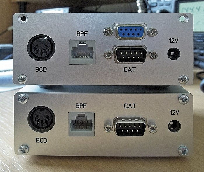 Backside in two different variants. Lower unit is showing the standard version while upper unit is having a “pass-thru” serial port (see below) in a bigger enclosure.
The BCD interface is constructed bi-directional, i.e. it can be used as an output if used in conjunction with the Kenwood CAT firmware or as an input if used with the BCD decoder firmware. In that case the serial port is disabled and just the BCD input signals are decoded and the dedicated band outputs mentioned above are provided.
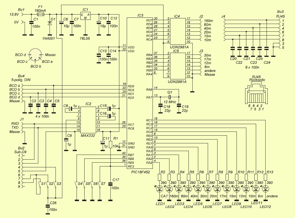 Schematics are shown left (click to enlarge). The PCB was developed on a double-layer board and all components fit directly to the PCB, so no external wiring is needed. I design all my PCBs using “SprintLayout” by Abacom. The PCB file is available for free (for privat use only! – if you want to use it commercially ask me, it’s copyright protected), click here to download. Abacom offers a free viewer software and most of the bigger PCB manufacturers accept LAY files for production, too.
The PIC needs to be “burned” just once with a bootloader firmware. If that is done you can do all subsequent firmware loadings thru the serial port using the mikroBootloader by Mikroelektronika. So after you burned the PIC you need to install either the Kenwood CAT firmware or the BCD firmware thru the serial port. Therefor connect the banddecoder to a PC where mikroBootloader is running using a cross-over serial cable. Put switch S6 to ON, start the mikroBootloader, choose PIC18 as MCU type, set speed to 115 200 Baud, press the S7 push-button on the PCB and press the CONNECT button in mikroBootloader within 5 seconds. Everything else should be self-explainatory. When firmware upload is done put S6 back to OFF and press S7 again. PIC will reset and restart with the just loaded firmware.
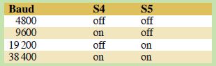 Switches S4 & S5 allow you to configure the serial speed the PIC is using to communicate with the radio according to the matrix right. Pay attention that you need to configure the same speed in the banddecoder as well as the radio! Some older Kenwood radios might need CTS/RTS serial signalling for their serial ports to work. If you set S1 to ON both connections will be bridged and the signalling will be permanently on. S2 & S3 offer you to also put + 12 V on RTS and DTR respectively to provide operating voltage for older serial interfaces for connection to older Kenwood radios that do not have real RS-232 ports. The possibility is there by design but due to lack of old radios I never tried that myself so use it with care, no guarantee from my side!
All blocking capacitors are SMD types 1206, so the biggest SMDs available and quite easy to solder. They are soldered on the PCB’s bottom side. All other components are thru-hole. All the components are available from Reichelt Elektronik, the components list with article numbers is available here.
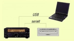 Connecting the banddecoder is possible in two different ways: For radios that offer RS-232 and USB like the TS-590 you would connect the banddecoder to the serial port while the USB port would be used for CAT control thru a PC like shown left. Both radio interfaces work in parallel and can even be configured for different serial speeds, i.e. 38k4 baud serial and 57k6 on USB.
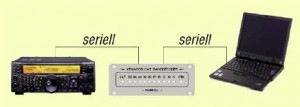 If your transceiver just offers one serial port things get a little more difficult. In this case you would have to “daisy-chain” the serial connection thru the banddecoder as shown right. On the PCB you got the connector J1 for exactly that case. It is holding TXD, RXD & GND signals in parallel to the on-board connector. That will work as long as a real serial port at the PC is used (serial to USB adapters will not work) and as long as the serial port on the PC end is opened, i.e. in use by a logging or CAT control application. As soon as you switch off the CAT control on the PC the serial port will have permanent levels that will pull down the banddecoder, too. So that is a small trade-off. Nevertheless it works without a problem on the TS-2000 of one of our contest group members.
A better idea would be to make independent ports, i.e. push all data traffic thru the PIC and separate serial ports to avoid that problem. That might be a project for the future. Our main goal was to have a solution for our TS-590 and that is working perfectly well using serial & USB in parallel – mission accomplished. 😉
If you have any questions don’t mind to ask:
![]()
Disclaimer: Please accept that we do not take any responsibility for any system damage you do on your own equipment while using this solution. It has been thouroughly tested over a few month’ time and worked flawlessly in all respects. But we can ofcourse not ensure that you do everything right when building up the pcb. Commercial use of any of my ideas or project parts (pcb, schematic, software) is strictly forbidden and protected by copyrights! But you can use everything for private use only, no problem. If you are interested to produce a commercial solution please get in contact using the above mentioned e-mail adress, thanks.