
Some time ago Sandro, DD3SP, asked me if it would be possible to create a small unit showing the actual Grid Square Locator based on GPS data. He had been to Sweden to enjoy some holiday together with VHF radio where you need to know your own locator to calculate bearings, distances, etc.
As I had been to some VHF expeditions myself in the past his idea was appealing as during my expeditions I always had to take a GPS receiver, get the longitude & latitude and then calculate the locator with a laptop or PDA afterwards – quite inconvenient, isn’t it?
So I started searching for some small GPS modules to get the GPS data, read it with a PIC, do the math and showing the results on a small display. I ended up with several hardware realizations. What you see above is the final one which has also been described in the FUNKAMATEUR magazine, issue 4/2009, and was available as a kit.
Navilock produces some nice OEM GPS modules. I have tested the NL-501 (Sirf3 chipset), NL-504 (MTK chipset) and NL-507 (µBlox chipset) myself. They do not differ much from each other (slightly different operating voltages), sensitivity is almost the same. So basically one has the choice which one to use. Myself I’m using the NL-501 and NL-504. The NL-501 Sirf3 chipset module is also available for the kit.
All the modules put out NMEA compliant GPS data with 9600 baud speed levels on a 2,4 V TTL interface. So with some level shifting from 2,4 to 5 V what a PIC needs as input it is rather easy to read the NMEA sentences. I then extract all needed information like latitude, longitude, height, speed, date, time, number of satellites for fix, etc., do some calculations and formation and present the data on a small 2 x 16 characters display.
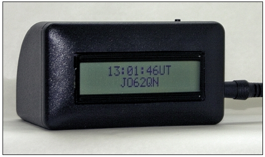
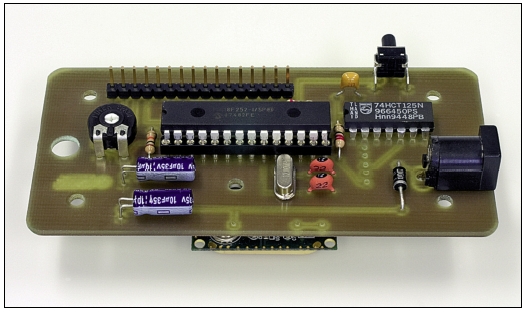
Hardware-wise the whole thing is quite easy as all the logic is in the PIC software. I made up a small PCB where you solder all the needed components. The 2×16 display attaches to this “main board” on top while the GPS module is soldered on the backside. This way you get one complete unit which nicely fits into a small plastic enclosure as you can see above.
You can set the display contrast with a small pot which is accessible from the back through a small hole thus making it fit your own taste after everything is mounted. The display is back-lit, ofcourse.
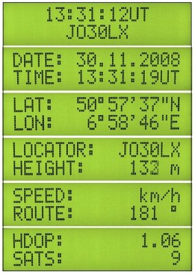 Shown on the left hand side you see the different displays which are available. After the unit gets its power it always comes up with the first one shown: current UTC time and the grid locator, probably the most important information that a radio amateur on the move needs.
The second one shows the date and time again, both are in UTC ofcourse.
On the third one you’ll see latitude and longitude in the degrees / minutes / seconds format. This is calculated from the GPS data as well as usually the GPS sets work with degrees / minutes / decimal minutes only.
The fourth display page shows the WWL as well as the height. Ofcourse I took the different counting scheme relations between lat/lon and locator (ascending vs. descending lat/lon within a grid square) on the Northern and Southern hemisphere and West and East of the 0° meridian into account. Thus the unit will work flawlessly worldwide and is suitable for the American Rover contest operations, too.
Fifth you’ll find your speed and heading when moving.
Last but not least the sixth display gives you the number of satellites which are currently used for the GPS fix as well as the current HDOP value. HDOP stands for Horizontal Dilusion Of Precision thus making it easy to judge how good the position accuracy is. An HDOP below 4 is good already, below 2 is very good and around 1 is almost perfect so to speak.
You can change between the different displays using the small button on the upper side of the unit which you can also see on the pictures above. A single button press changes over to the next display cycling from 1 to 6 and then starting from 1 again. So as you can see the user interface is as simple as it gets – really nobody should have problems using it. 😉
In issue 9/2009 of the FUNKAMATEUR magazine I described a slightly revised version that also includes a Bluetooth module! It is optional but if you solder it to the PCB you can also use the NMEA data over the BT link on a laptop computer, PDA or smartphone for APRS, navigation, GPS log, or whatever other GPS application might be useful to you. Furthermore the 4th display has been changed to show the Extended Locator instead of the “normal” one.
The GPS display was available as a kit through FUNKAMATEUR’s webshop for a few years. Unfortunately it’s not produced anymore. Therefor I’m not bound to the contract anymore and can provide the software, schematics and PCB layout for download now – good for you, if you want to build your own. 😉
My GPS display is now a permanent companion in my car. Especially when doing long journeys on the German or European highways it is quite interesting to follow the locator display and suddenly see well known grid square indications from QSOs you’ve done before. Looking out of the window you immediately get an impression of the area where your QSO partner was/is located in. I like that very much – it’s like a nice entertaining game. 😉
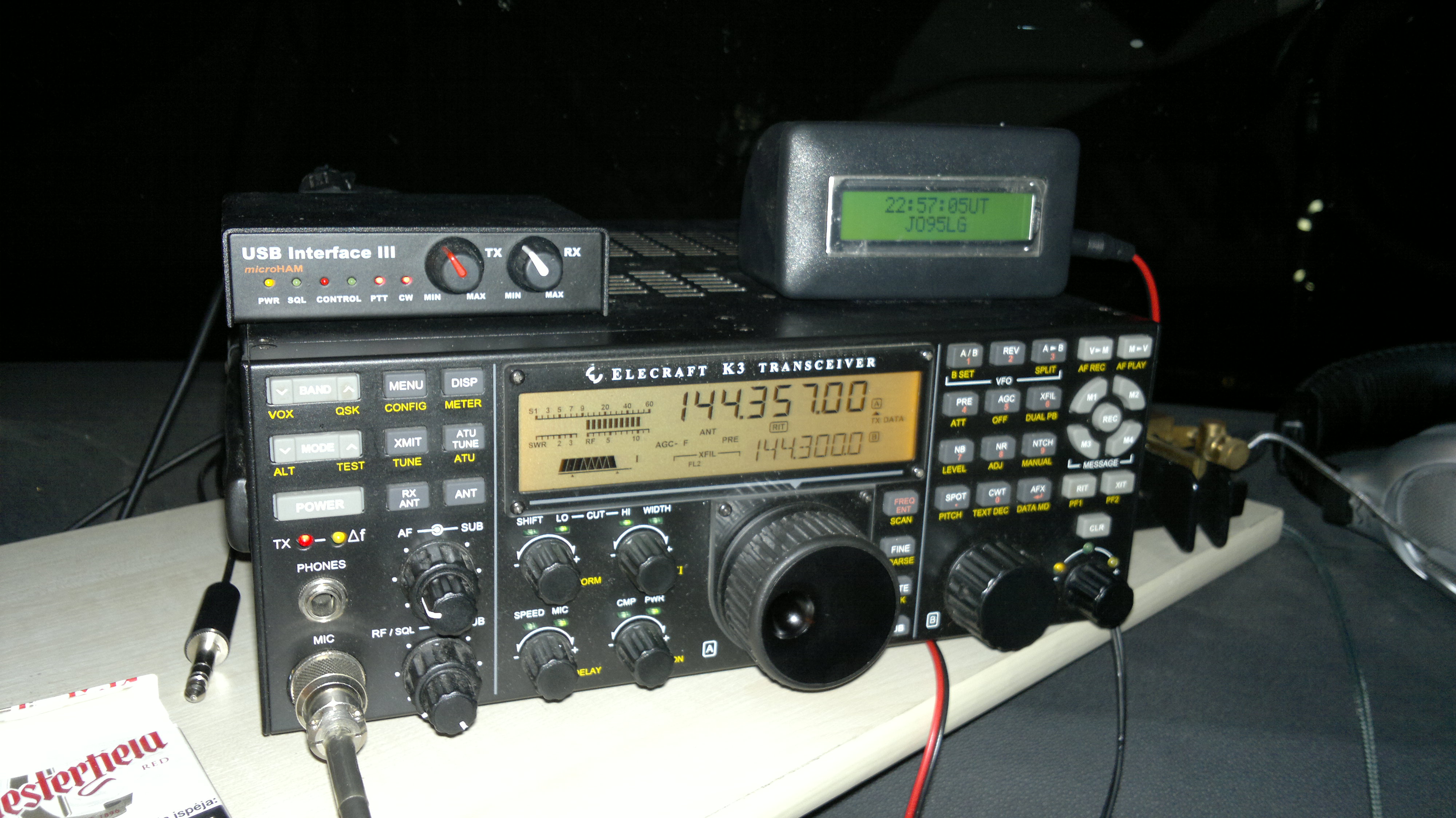 It proved very useful on our 2013 maritime mobile trip across the Baltic Sea, too, see photo left. Besides this the GPS display already helped me several times now to find a suitable portable location in certain squares. You always know where you are! I even use it for regular navigation work with my Bluetooth-coupled mobile phone and a navigation application on it.
So have fun building and using your own one!
Disclaimer: Please accept that we do not take any responsibility for any system damage you do on your own equipment while using this solution. It has been thouroughly tested over a few month’ time and worked flawlessly in all respects. But we can of course not ensure that you do everything right when building up the pcb. Commercial use of any of my ideas or project parts (pcb, schematic, software) is strictly forbidden and protected by copyrights! But you can use everything for private use only, no problem. If you are interested to produce a commercial solution please get in touch using the above mentioned e-mail adress, thanks.