
I was a proud owner of Icom’s IC-7000 transceiver for a few years. The ‘7000 is a feature-rich and powerful radio. Besides the superb DSP features things I liked the most were the internal CW and voice keyers. I used them extensively during contests and saved the extra sound card interface and cabling to use e.g. a software voice keyer from the contest logging program and possible problems due to stray RF getting into the sound cables.
 BUT: There’s one minor flaw. While the Icom engineers built in a repeat mode for the CW keyer (i.e. you can choose that a CQ call shall be automatically repeated after a defined time) they simply let this repeat mode out of the voice keyer! Oh what a shame … still wondering what the engineering geeks were smoking while programming the voice keyer feature. 😉
Being into some PIC programming myself (as you can see on the other pages of this website) I designed a small external unit to over-come this drawback. And while designing the hardware for it I also included possibilities to attach a headset and a foot switch PTT for some more convenient contesting than just using the hand-mic.
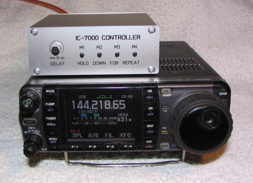
As you can see above the result is a nice looking small external unit. It is usable for the internal CW as well as the voice keyer. Operation is quite easy: Press the according memory button shortly to play the selected message once. Hold down the message button for 1 second and it will play the selected message in repeat mode. You can choose the wanted repeat delay, i.e. the time between playing the messages again, between 0 and 30 seconds using the pot on the front’s left hand side. Stopping playback is possible by either pressing one of the message buttons (no matter which message is currently playing) or through stepping onto the attached foot switch. This works during playback as well as during pause times.
The foot switch and headset’s mic and phone lines can be connected on the unit’s back side. My design uses buttons and sockets directly soldered onto the PCB to ease assembly but that’s up to individual desire, ofcourse. I chose an RCA connector for the foot switch while the headset plugs into 1/8″ (3,5 mm) phono stereo jacks. This way you can use the original connectors of e.g. computer headsets. I used a rather cheap one but with superb audio quality – at least people asked on the air what I’m using to produce such a good sound. 😉 As Icom is already providing the needed voltage on their mic line (they use electret capsules in their own microphones, too) we do not need to provide extra voltage to make the computer headset’s mic capsule work. So as you can see it does NOT need to be a Heil headset all the time. 😉
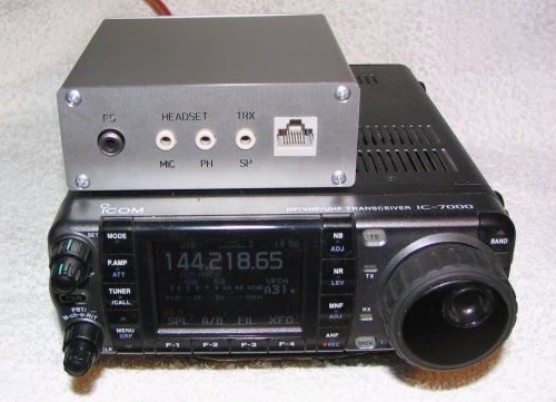 To get the sound into the headset there’s another 1/8″ jack jumpered to the headset phone jack. You connect this one to the radio’s speaker port and be done. Last but not least you see an RJ-45 socket on the right hand side. Simply use a standard network cable to attach to the transceiver’s back side mic port. Commands to the transceiver for playback of the memories as well as PTT, mic, voltage and ground are routed through this port. As the whole circuit does not need more than 4 mA it is no problem to take that current from the mic jack which is providing max. 10 mA per specs. The transceiver’s 8 V are down-converted to 5 V for the PIC then.
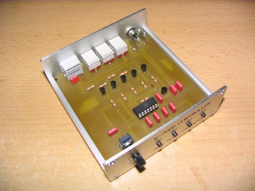
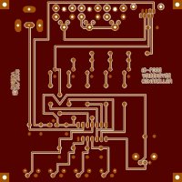
The PCB was designed spaciously at 100 x 100 mm. This way it fits perfectly into the nice looking enclosures of Fischer Elektronik. For the German readers: These enclosures are available at Reichelt Elektronik, search for article number KOH-1100 which I used for the lower enclosure half, KOH-2100 for the upper half and DPL 1-2 for a set of front and back covers plus screws. Outer dimensions of the whole enclosure are 105 x 39 x 105 mm (W x H x D). Of course you could use any other encloure, too, i.e. just using the PCB and wire buttons, pot & jacks “externally” in an enclosure that suits you more.
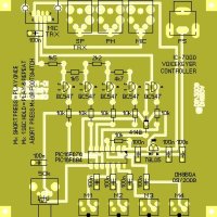
As you can see in the circuit diagram and on the PCB components layout I used blocking capacitors even on the short lines between the push buttons and the PIC microprocessor. Basically it is not needed when in a metal enclosure but on the other hand it does not hurt. If you put the PCB into a plastic enclosure (not recommended, we’re talking RF here) you might need to block the base of the transistors, too, if you encounter RFI problems. Simply put 47 or 100 nF capacitors from base to ground. I did not experience any RFI trouble with this circuit yet even running American legal limit power for testing but that’s with the metal enclosure, ofcourse. 😉
 The used BC 547 transistors are common low cost NPN types in Germany / Europe. You can substitute them with any NPN transistors capable of switching a few milliamps.
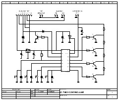
The main heart of the circuit is the PIC microprocessor. I used a 14 pin variant here, the 16F676 or the 16F684. It features an A/D analogue to digital conversion module which I use to measure the voltage over the 50 k delay pot between messages on pin 8. All other ports are digital I/O. The firmware checks in a loop if one of the message buttons was pressed and if so, how long (to distinguish between play once and repeat mode). The same applies to the foot switch line. If a signal (line going to ground) is detected there the PIC will generate a PTT signal through transistor T5 to the transceiver. The IC-7000 measures it’s internal voltage on pin 2 of the microphone connector. Depending on the selected message the PIC puts a ground signal in between the resistor array on pin 2 of the microphone jack with the help of the transistors T1 to T4 thus changing the measured voltage in the ‘7000. This way the transceiver knows which message was selected and starts the playback of the according message. This is exactly what is described in the operating manual, too, the only change being that the switches shown in the manual were substituted by the transistors T1 through T4. They will switch ground after getting a signal from the PIC processor.
If in repeat mode the PIC takes care of the repeat delay and recalls the same message from the transceiver after every delay period. Thus it has to save a temporary marker with info which message was played last. During pause time as well as playback the firmware permanently checks if there’s another button press or foot switch press. If so while messages are playing it will send a signal to the transceiver again to stop the current playback. If so during pause time it will simply stop the internal repeat mode.
As you can see the needed logic is quite easy. One really has to wonder why Icom missed that in the IC-7000’s internal firmware …
BTW: You can ofcourse use the “IC-7000 Controller” in parallel with your normal hand-mic, i.e. connect the mic to the transceiver’s frontpanel and the controller to the transceiver’s mic jack on the back to take advantage of the voice keyer repeat mode while still using the HM-151 hand-mic and all it’s features. But, you should not connect hand-mic and headset in parallel then as both mic ports of the transceiver are wired in parallel internally. So you will pick up your own voice once from the HM-151 and once from the headset which might not sound too good in parallel. 😉
Well, now here’s everything you need to build your own one:
- Circuit diagram – you may want to understand what you’re doing there, won’t you? 😉
- PCB layout – select “none page scaling” in Acrobat reader’s printing options to ensure the printout measures exactly 100 x 100 mm.
- PCB components layout – just to show you where to solder what.
The front and back panels you see on the pictures above were produced commercially by Schaeffer AG. They are not cheap but as in the German saying “Das Auge isst mit.” which can be best translated as “The sizzle sells the steak.” you know the eye must be pleased as well. ;-)) If you download their Front Panel Designer software (free of charge and good to design some other front panels, too, or simply print them out and use as a drill template) you can use my front panel and back panel design to order front and back panels there. Ofcourse you are free to change the labeling, etc.
Let me know if you have any questions:
![]()
Disclaimer: Please accept that we do not take any responsibility for any system damage you do on your own equipment while using this solution. It has been thouroughly tested over a few month’ time and worked flawlessly in all respects. But we can ofcourse not ensure that you do everything right when building up the pcb. Commercial use of any of my ideas or project parts (pcb, schematic, software) is strictly forbidden and protected by copyrights! But you can use everything for private use only, no problem. If you are interested to produce a commercial solution please get in contact using the above mentioned e-mail adress, thanks.