No condx today so I used the time to finally cobble the rotator interface together that I bought from remoteqth.com last December together with the Band Decoder II. It’s a neat kit not too expensive including a nice enclosure. I could not do it cheaper myself besides all the time needed so why not use what’s available on the market already. 😉
The kit comes with all parts included. It consists of two PCBs that need to be soldered with through hole components only. It also includes an Arduino Nano which holds the firmware and all logic. You only need to solder the pin strips on that one. It took about an hour to complete everything, easy going soldering-wise. 😎
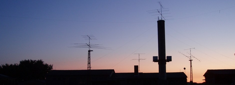
Ready soldered display unit
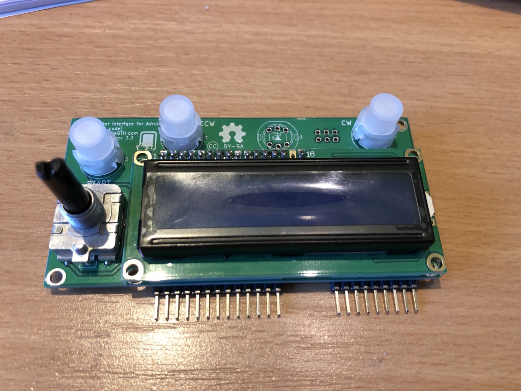
Main board without the Arduino Nano yet
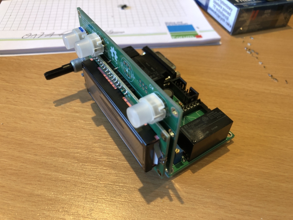
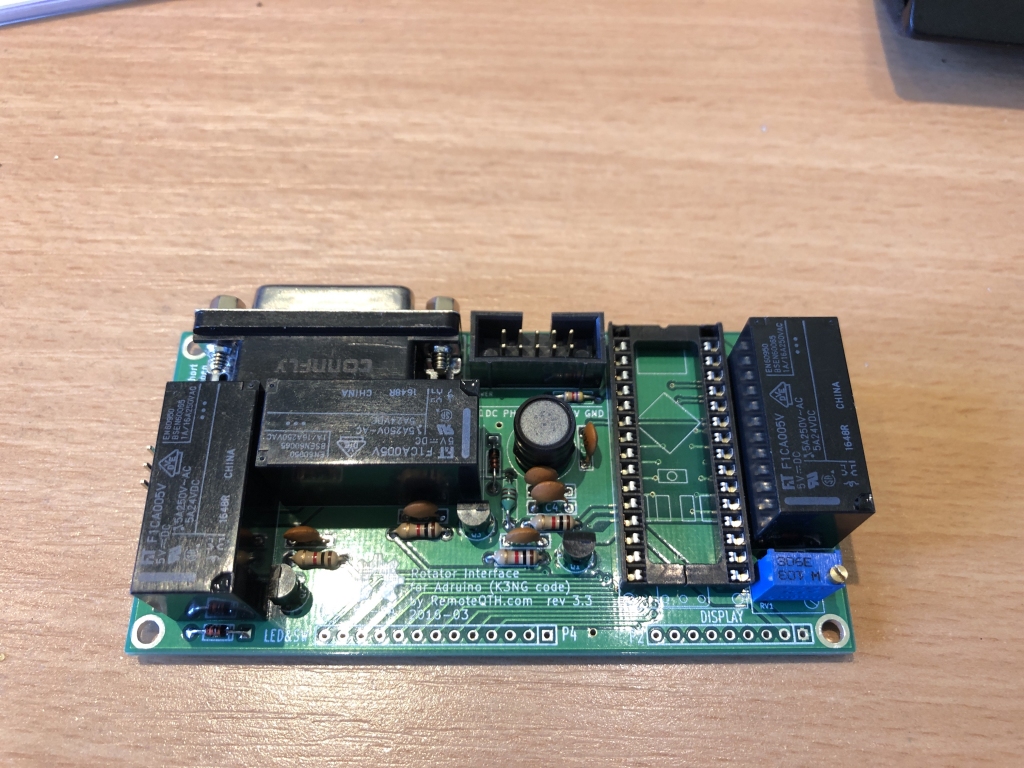
Both PCBs cobbled together
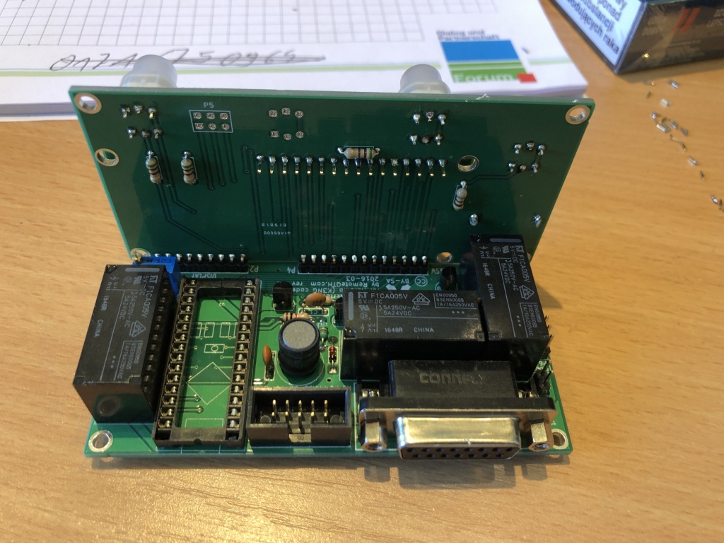
Both PCBs cobbled together
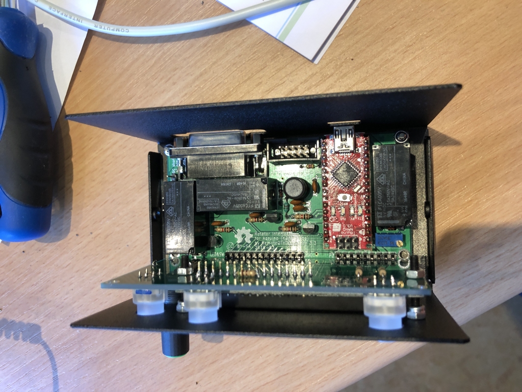
Mounted in the enclosure
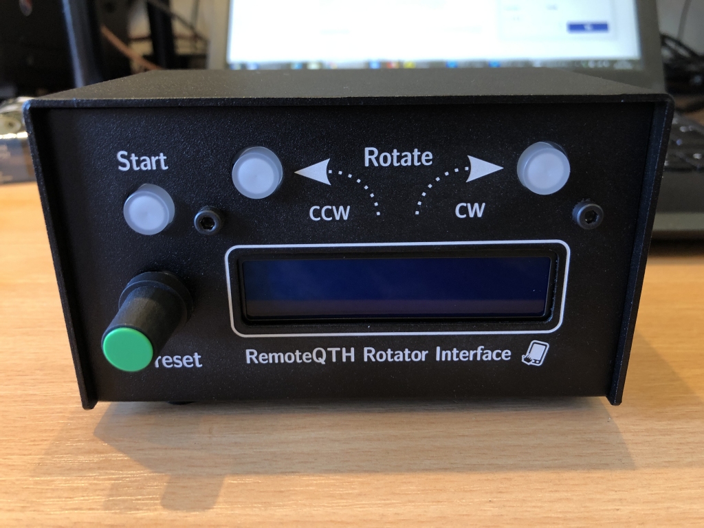
Professionally looking, that’s for sure!
My idea was to use it together with the Raspberry Pi based RemoteQTH server and then not just this one but 4 four of them to control all of our rotators from a simple web interface. I do have the rotator interfaces by DF9GR in place that have been working perfectly well for a few years now already (can highly recommend them!) but do require Windows software and virtual COM port drivers at the control side to be used. I wanted to become a little more OS independent, i.e. having it all web-based and thus being able to use whatever OS is available including Android, iOS and MacOS besides Windows to be more flexible at the control side. On the other hand it’s quite expensive to buy/build 4 of these interfaces plus the RaspPi so another approach might be to just set up a small PC at the remote side or even in the cloud that holds all the Windows software (I need a Windows program to switch on the 2 m amp, too) and gets connected to by RDP which is available on all platforms. Just need to think it through for another while. 😉
Back to the remoteqth.com rotator interface. I had some trouble getting it all to work. Three main issues:
First the interface is configured for a South end stop by default. It took me almost an hour to find out how to change that as all of our rotators have their end stop at North and are 450° capable. Modifying the Arduino firmware didn’t do the trick as I had expected (I probably missed some code to change). It turned out there’s a command to do it (that was easy to find) when connected serially and yet another one (that was hidden in the source code and only found by coincidence!) to also save it to the EEPROM so it’s a persistent setting. There’s a lot of documentation on the web (the interface is based on the K3NG code) but nowhere a single page where you get all the options at once (or I was just to stupid to find it, hi).
Second thing is the calibration. By default you can only calibrate 0° and 450° (also through serial port commands only!) and all values inbetween are calculated by the firmware. Now we all know that no potentiometer is really linear (except maybe the more expensive and/or 10-turn ones usually not used in rotators) so there are a few directions where the heading is off by a few degrees. It is probably acceptable on the rotator tested with overhere but could be a problem elsewhere. You can correct it by measuring the voltages inbetween and then setting up a correction table in the firmware, compile it and upload it to the controller. Well, that’s not for the faint-hearted! I do have some experience with PIC programming and doing it on an Arduino is not too different but thinking of all the average Joe’s I’m not sure if this really is a “mass market” solution. Rather for experienced DIY’ers …
Third problem is I do not get stable direction readings yet. 🙁 The interface is powered from the USB port but it does not matter if it’s from the PC, the RaspPi or a powered USB hub, readings are not stable but varying by +/- 7 degrees all the time and +/-20 degrees every now and then. It probably is a voltage problem somewhere but I did not have a known-to-be-stable external 5 V power supply at hand here at the radio station so this one will have to wait a little longer to be checked in detail (all of my power supplies and measurement stuff are packed for our move already).
I have to say I was quite a bit disappointed with the outcome and these problems as I had expected a directly and perfectly working unit and not needing to dig into the source code etc. first. At least this was my expectation after our great experiences 😎 with the DF9GR ERC rotator interfaces (we built 6 or 7 of them in the past, always easy going, never a problem and well documented). On the other hand all Youtube videos on the remoteqth.com interface do show stable readings so it must be something overhere. I would not blame remoteqth.com, they are just providing the hardware kit and do rely on the K3NG firmware, too. Nevertheless a little disappointing … Will check into it later again, probably in autumn when all set in Hamburg and having all needed tools available again …