Holidays now! 😎 Decided to visit my goddaughter Anna-Lena (now 4 years old or better young ![]() ) near Frankfurt/Oder. Her father is my good friend Sandro, DD3SP. While there he mentioned interference of S5 to S7 between his 50 and 70 MHz rigs (he had just modded his old FT-847 for 4 m). As I had recently built a coax-based diplexer for 50/70 MHz (a G4SWX idea) to use the same (dualband) antenna on both bands without needing to switch anything I suggested to build a coax-based 50 MHz notch filter. The principle is based on coax stubs also used on HF to minimize interstation interference. As Sandro had a few meters of RG-213 MIL-C17 left over we used that to build it. As it turned out his coax had a velocity factor of 0.66 while the RG-213UBX I had used myself before had 0.67. That’s already “good” for a few centimeters difference! Seems it was a good idea to bring my FA-NWT network tester along when visiting him. 😉 We also made good use of my Elecraft XG3 signal source to fine-tune his 4m pre-amp.
) near Frankfurt/Oder. Her father is my good friend Sandro, DD3SP. While there he mentioned interference of S5 to S7 between his 50 and 70 MHz rigs (he had just modded his old FT-847 for 4 m). As I had recently built a coax-based diplexer for 50/70 MHz (a G4SWX idea) to use the same (dualband) antenna on both bands without needing to switch anything I suggested to build a coax-based 50 MHz notch filter. The principle is based on coax stubs also used on HF to minimize interstation interference. As Sandro had a few meters of RG-213 MIL-C17 left over we used that to build it. As it turned out his coax had a velocity factor of 0.66 while the RG-213UBX I had used myself before had 0.67. That’s already “good” for a few centimeters difference! Seems it was a good idea to bring my FA-NWT network tester along when visiting him. 😉 We also made good use of my Elecraft XG3 signal source to fine-tune his 4m pre-amp.
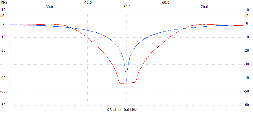 The graph nicely shows what happens. The blue line is just one quarter-wave open stub trimmed to 50.060 MHz. To even higher the attenuation a bit one should use additional quarter-wave length’ of coax for the connections on the to be notched band, i.e. 70 MHz antenna port – quarter-wave for 50 MHz – connection point of the quarter-wave open stub for 50 MHz – another quarter-wave length for 50 MHz to the 70 MHz transceiver. The quarter-wave sections will transform the already high impedance of the open quarter-wave stub to even higher impedances at the antenna/transceiver ports. Thus we will gain another few dB’s of attenuation. Will try to draw a picture for even easier understanding if a bit time during holidays. 😉
You can get a notch depth of about 41 dB with one stub connected as described above but as you can see it is really small bandwidth only! 41 dB notch depth on 50.060 MHz means only 30 dB of it is left about 150 kHz higher on 50.200 MHz! So we need to broaden it a bit to have a more consistent performance across the whole band. Another problem with just using one single stub is as 50 and 70 MHz are not too far apart you will still see an attenuation of about 2 db on 70 MHz – that’s definitely too much!
To solve these two issues you “simply” connect a second stub. That one must be matched to the first one and the matching “circuit” should also lower the attenuation on 70 MHz. By coincidence the matching section is just a bit shorter than a quarter-wave on 6 m. Besides ensuring a low insertion loss on 4 m (only 0.20 dB) it also results in an almost flat and broad (about 4 MHz) notch response curve (see the red line in the picture above) and gives another 3 dB additional attenuation, thus 44 dB in total. By the way, the small hump on the left side of the flat notch is due to a small discrepancy in the resonance of the 2 stubs. While the first one was tuned for 50.060 the second one was tuned to 50.120 MHz (ooops, cut off a bit too much ![]() ).
).
Connecting the filter inline with his 4 m antenna all interference is completely gone now. Mission accomplished! 😎